TicTocTrac
DocumentationWhat we've done
TicTocTrac
Don't just track time, track your perception of it!
Designed by Brian Schiffer and Sima Mitra
Cornell University - ECE 4760 - Spring 2012
http://www.TicTocTrac.com
Documentation last updated on September 21 2012.
Check Us Out!


Introduction
Time flies when you're having fun....
Thoughts like, “Time flies when you’re having fun,” or “Lecture lasts forever,” originate from our highly variable sense of time. You have experienced this if you have ever checked your watch to discover that much more (or less) time has progressed than you expected. TicTocTrac is a wristwatch that doesn’t just keep time, but measures your perception of it, allowing you to track changes over the course of days or even months.
High Level Design
Project Rationale
Time, specifically its measurement, has fascinated humanity for thousands of years. As the devices we use to measure time have evolved, they have progressively become more elaborate and precise. NIST has a great page documenting the history of time. While time measurement itself is intriguing, perhaps even more fascinating is how we internally perceive time.
Our perception of time is distorted constantly every day. Most of us are familiar with the old adage, "time flies when you are having fun." This isn't quite true. A more accurate statement would be that our perception of time is proportional to the amount of new and intricate experiences we are observing. If you are practicing a new sport or working on a project that involves a lot of concentration then you perceive time as slower. Since you have been absorbing more information than usual, time seems like it has expanded and thus feels longer.
Then why do we often feel like time flies when we are having fun? It may be because it seems faster compared to when we are bored (and thus paying a lot of attention to the passage of time). A great list discusses this possibility as well as several other great facts about time. Personally, we think it might result from a desire to continue the fun activity after it is done, thus resulting in it the perception that it was too short of a time, regardless of the actual length of the activity. It has also been found that different types of music can cause time to slow down as you get caught up in the music. Video gamers would certainly agree with a study done that showed how time seems to speed up and pass you by when you become absorbed in a video game - a day may pass before you even realize it!
Not only does our time perception vary throughout our day to day life, but it actually speeds up significantly as we get older. Science isn't sure if it is because our brain is slowing down, experiences are becoming less unique, or if each experience is shorter in proportion to our life thus far. NPR examined this and even did their own experiment, finding that older people (over 60) would often estimate a minute to actually be a minute and a half!
There have been many psychological studies on time perception. Professor Dan Zakay has conducted numerous experiments on time perception. His 1997 article, Temporal Cognition, details four primary methods for measuring time perception:
-
Duration estimation
In this test a subject is given a start and stop stimulus. The subject is then asked to guess the duration between the two stimuli. This guess can be compared to actual time to determine the subject's current time perception.
-
Duration production - this is the method used by tictoctrac
In this test a subject is asked to wait what they feel is a specific duration after a start stimulus. The subject then signals when they believe the desired duration has passed. The time it took for them to signal is compared to the desired duration to determine the subject's time perception.
-
Duration reproduction
In this test the subject observes a duration between stimuli and is asked to reproduce this duration. This is similar to the duration production task, but instead of being told a desired duration they observe the duration first. Their reproduced duration can be compared to the original duration to determine the subject's time perception.
-
Duration comparison
In this test the subject observes two different durations and is asked to choose which one felt faster. Their choice can then indicate if their time became distorted while observing either duration.
The duration estimation is one of the simpler methods to use. There was a great year long quantified self experiment based around this method. The experimenter tried doing a new activity every day for a year and estimating how long he did that task. He later compared this to the video recordings of himself doing the event to discover how his time distorted. He discovered that over the course of the year he felt like he had experienced 14hrs more than the time he actually spent doing the activities. The duration production method is used by a simple android app that makes you try to guess when a certain amount of time has passed. TicTocTrac was initially designed to use duration estimation, but we decided to move to duration production for ease of use. This allowed the user to decide when they wanted to do a test and simply tap the watch to mark the end of the test.
In addition to the time perception measurements, TicTocTrac also keeps track of when you check the time. We know that when we are running late or bored in class we tend to check the watch maybe even several times a minute! We hope this data will show some great trends correlating with time perception.
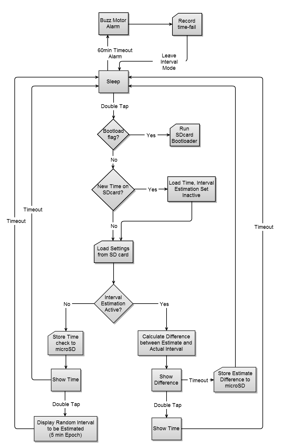
State Machine
Here is the overall flow of our program. This also serves to illustrate how the user can interact with the watch.
Relevant Standards
SD (Secure Digital) Card
SD cards commonly implement a simple SPI protocol to allow microcontrollers to interact with them. We used this to provide the storage space necessary for saving many measurements.
SPI (Serial Peripheral Interface) Bus
Serial Peripheral Interface (SPI) is a simple 3-wire interface with a chip select for each device. Both the SD card and the real time clock communicate with the microcontroller using this interface.
FAT16 (16bit File Allocation Table)
FAT16 is a basic file system with 16-bit cluster addresses. This is a commonly used file system that is easily controlled by 8-bit or 16-bit microcontrollers.
Tradeoffs
Consistency vs Usability
We originally intended to use duration estimation instead of duration production. Our reasoning was that we could alert the user via the vibration motor at random times and ask the user to input how long since the last alert. This would result in consistent data every day, but turned out to be problematic for a number of reasons. This meant the user would get alerted throughout the day even when they didn't want to be. It also required the user to take the time to input their estimation. The next tradeoff also details some issues we ran into with our method of data input. Overall, we found that by switching to duration production the user could choose when to start a test and simply tap to end a task. This was a much more user friendly system.
LED Sensing vs Reliability
As part of our original goal of using duration estimation we intended to allow the user to input their estimate via the LEDs on the clock face. We did have some success with light reflection sensing using LEDs during our initial prototyping. Unfortunately, when we created the PCB we tried to tie the LEDs together with two LEDs per a sense pin. This resulted in too much leakage current across the LED we weren't sensing and inaccurate measurements. With enough processing in software we might have been able to overcome this issue, but we decided it would be too inaccurate and may fail in brightly lit environments regardless. Instead we came up with our current implementation using only the piezo tap sensor and duration production. This resulted in a much simpler and more reliable system that still met all of our original goals.
Mass Storage vs Simplicity
We originally intended to implement a mass storage device on the watch. This way the watch could show up like a thumb drive when plugged in over USB. This is actually why we chose the atmega32u4 which has built in USB capabilities. Unfortunately, it did not always work consistently and caused issues when trying to run it at the same time as our own code. We found that it was just as easy to require the user to remove the SD card and much simpler to implement reliably.
Hardware
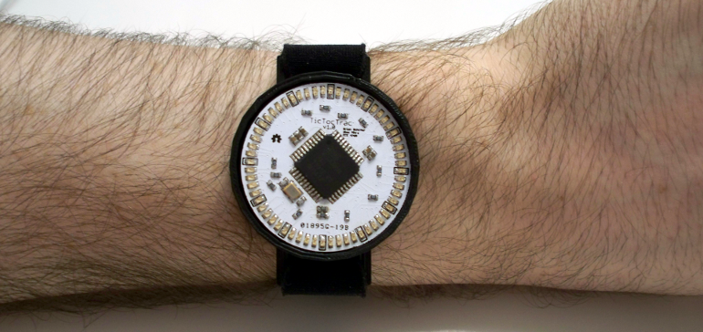
Contraints and Specifications
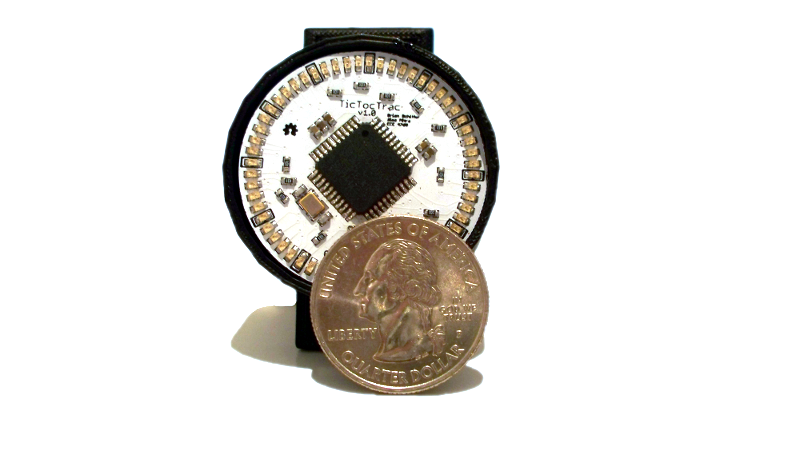
When we first began this project, we had very clear constraints and specifications in mind. We obviously wanted to make a watch capable of tracking time perception, but we also wanted it to be something people would enjoy using. This meant that the device needed to be about wrist watch size and be self contained with no protruding wires. We also wanted it to be sleek enough that people would be proud to wear it. To meet this goal we had some great PCBs manufactured by seeed studio before final project time even began. We also wanted it to be easily useable day to day, thus the USB data and charging capabilities. Finally, we needed the data to be easily accessible and understable. For this purpose, we created the TicTocTrac website. Overall, we wanted a small, useable, sleek device that allowed users to keep tabs on their time perception.
Division of Boards
In order to meet all of our constraints and specifications we decided to split the project into two boards. Separating the project into two boards allowed us to hide most of the circuitry inside the watch on the bottom board while keeping the top board clean and simple looking. The top board contains the microcontroller, the display LEDs, and the piezo tap sensor. The bottom board contains the real time clock (RTC), the boost converter, the mosfet for the motor, the charging circuitry, the SD card, USB connector, and the motor & battery connectors. The two boards are connected with a low profile header and socket to allow the microcontroller to talk to the peripherals and receive power. Further details on each of these boards can be found below.
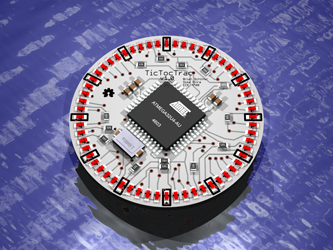
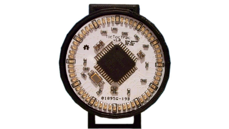
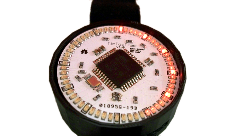
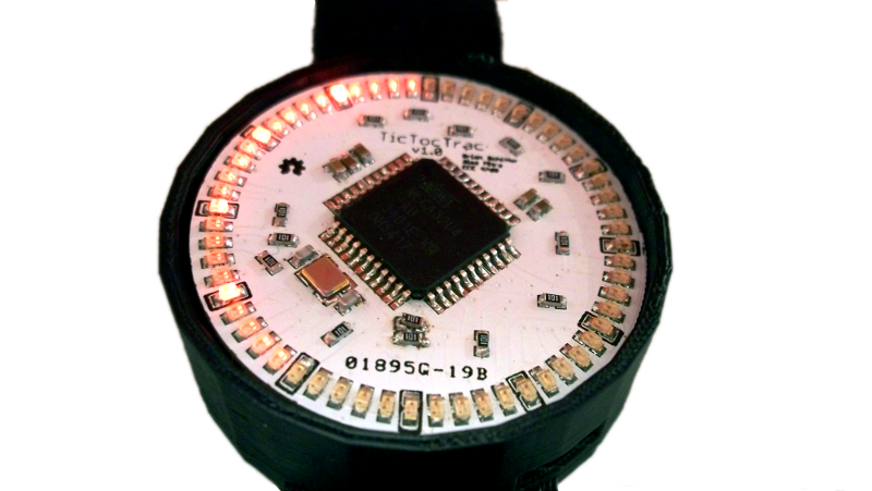
Top Display Board
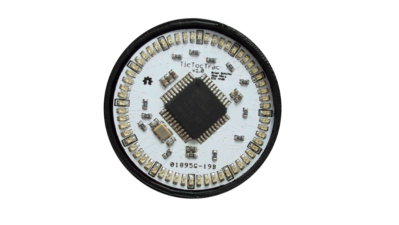
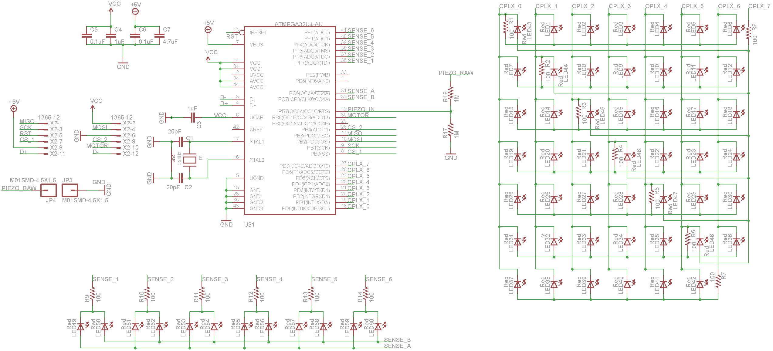
The top board is a PCB we had fabricated by Seeed Studios. It contains 60 LEDs for display, the main microcontroller and the external oscillator. We are able to control all the minute LEDs via a multiplexing scheme called Charlieplexing. Charlieplexing relies on the tri-state logic of microcontrollers to connect large numbers of LEDs together in banks while still allowing for individual addressing of each LED. The hour LEDs are arranged in an array we designed when we initially thought we were going to use LED sensing for input.
Internal Hardware Features
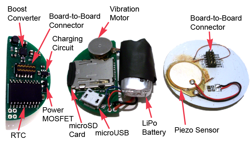
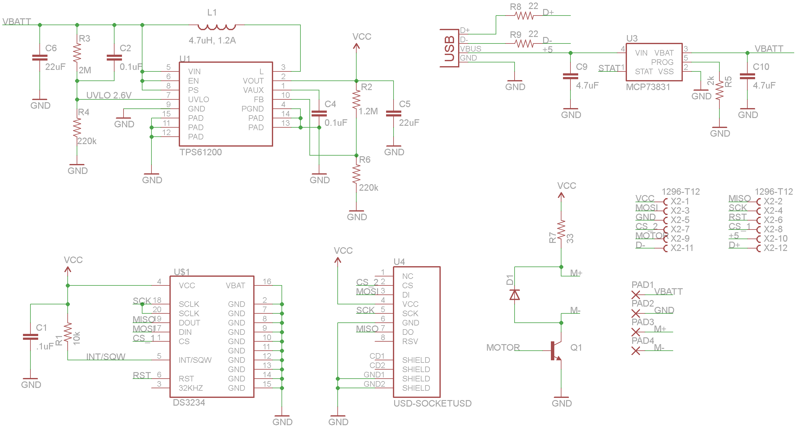
(From left to right) Front of Bottom Board, Back of Bottom Board, Back of Top Board showing the internal features of each. The boost converter (TPS61200) takes the variable battery voltage (2.6V to 4.2V depending upon charge) and regulates it up or down to a constant 3.3V. The charging circuit uses a dedicated LiPo charging IC (MCP73831T) to safely charge the battery. Since the vibration motor consumes more current (100mA) than the microcontroller can provide over I/O, a simple N-Channel MOSFET (2N7002) to control it. The real time clock (DS3234) highly accurate time keeping using a temperature compensated internal oscilator even when the microcontroller is sleeping. The microSD card is used for all data logging and settings, as well as bootloading new firmware onto the microcontroller. The microUSB is used for charging the LiPo, but is wired to the microcontroller in case we ever want to implement USB capabilities. The Piezo sensor is a simple piezo electric element we use for tap detection.
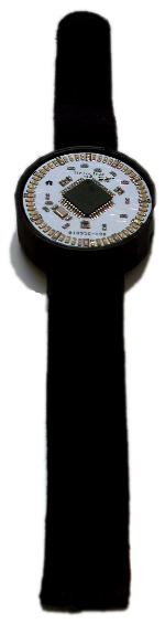
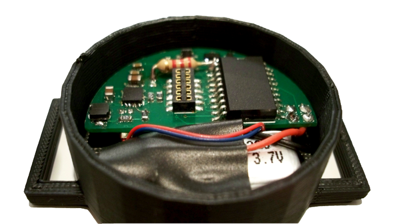
3D Printed Case
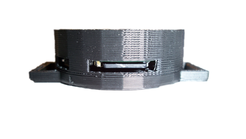
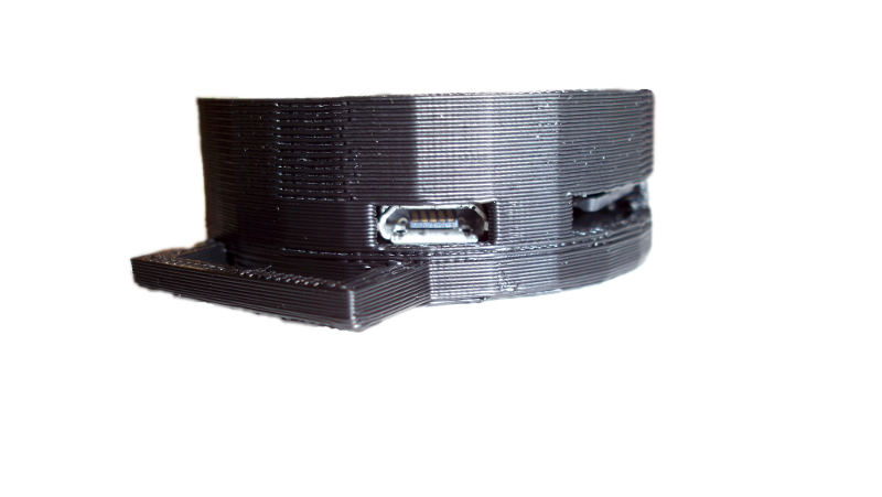
In order to make our project actually wearable, we designed a case in sketchup. A friend and classmate, Jeremy Blum was nice enough to let us use his makerbot3D printer to make a case! We were careful to leave room for the USB charging cable and the SD card. We have successfully been able to use TicTocTrac, complete with charging and data recording/upload, without having to remove it from the case. This definitely gave a TicTocTrac a more finished feel. Thanks Jeremy!
Assembly Instructions
- 1
Assemble Tools
To make your own TicTocTrac, you’ll need: a soldering iron with SMD appropriate tip, tweezers, solder paste, small SMD solder, and flux. We also found it useful to have tack fluid and a desoldering braid on hand.
- 2
Download the Eagle Files
Download the latest eagle files from our repository.
- 3
Check for Revisions
We are constantly improving our design, so be sure to check out our revisions page and make the appropriate changes to the schematic.
- 4
Order PCBs
We suggest ordering the PCBs from SeeedStudios, a low priced fabrication service great for small projects. Turn-around time is about 20 days.
- 5
Order Parts
Order the rest of the parts on the Bill of Materials from Digikey and Sparkfun. We suggest getting extras of all the parts, expecially the Atmega32U4, boost converter, and LiPo battery.
- 6
Populate the PCBs
Don’t forget to check for revisions! Instructions on how to solder the QFN package and reset a shorted Lithium Polymer Battery are on a separate page. We soldered all the componenets on by hand, but it is possible to use solder paste and toaster oven instead.
- 7
Program the Bootloader
Once you have an assemble top and bottom board, you can flash on the bootloader. You will need to make an adaptor to connect the board-to-board on the top board to your ISP due to the differences in pitch size.
- 8
Format the SD card
Format the microSD card to use the FAT16 file system. You are now ready to add the necessary files to the SD card.
- 9
Write to the SD card
You will need to add 2 files to your microSD card: tictoc.bin (a binary file of the compiled project) and settings.dat (a settings file). To force the first bootload, unplug the top board from the bottom board, pop the SD card into the bottom board and reconnect the top board.
- 10
Enjoy your TicTocTrac!
Charge your LiPo battery over the microUSB. Your watch will record your time perception measurements and the number of watch checks, saving this information to tictoc.csv on the microSD card. You can upload your data to our website and see how others percieve time!
Software
Our entire code can be downloaded as detailed in our downloads section. We carefully developed our code step by step developing libraries for each aspect of our project before finally writing the main file for TicTocTrac. This resulted in some great modular libraries and a simple main file. The libraries we created were:
- display.h - This contains functions for the display, including showing the current time.
- motor.h - This contains functions to turn the vibration motor on or off.
- piezo.h - This contains functions detect single or double taps via the piezo sensor.
- rtc.h - This contains functions for the RTC and was heavily based off of an arduino library for the ds3234.
- sd.h - This contains functions to write data to the csv file or load settings from the dat file.
Particular high level details of our software are detailed below. Please download our commented code if you wish to read the exact C implementations.
Time Display
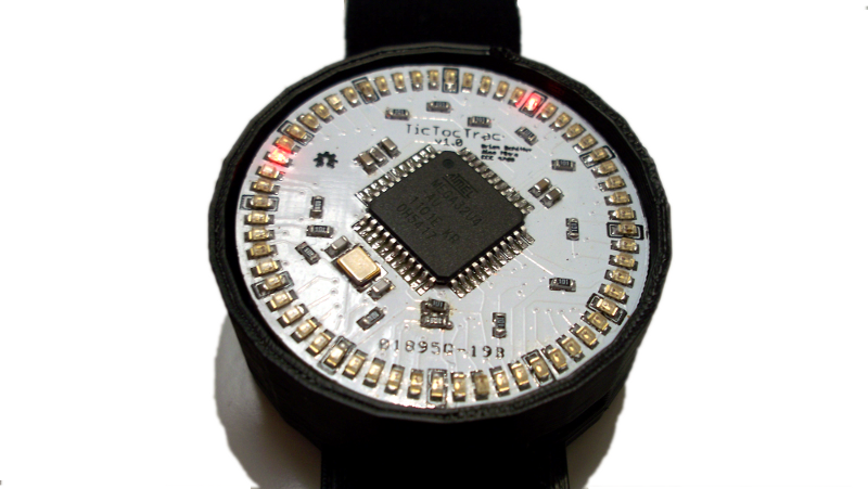
TicTocTrac functions as an analog LED watch. When the face of the watch is double-tapped, the watch awakens from sleep mode and displays the time. Hours are delineated by stead illumination while minutes blink. If the watch face is not double-tapped again, it returns to sleep mode to conserve energy. Every time the user checks the time, this event is time-stamped and logged to the SD card.
To set the time the user saves the current time to the settings.dat file on the SD card and sets the current-time flag. Upon the next double-tap, the watch will load this new time to the real time clock and clear the current-time flag in the settings file.
Since the microcontroller has a limited number of IO pins, we used a Charlieplexing scheme which allows us to illuminate every LED, but only one at a time. To give the illusion of concurrency, we quickly cycle between which LEDs should be illuminated. Charlieplexing is a multiplexing method based on connecting the LEDs in a special pattern. To illuminate a single LED, the anode and cathode lines connecting to it are set to outputs while the rest of the Charlieplex lines are set as inputs without pull-up resistors, effectively disabling the rest of the LEDs. This will leave two LEDs that can possibly be illuminated, depending on which output is set high.
Interval Task
To measure time perception, we decided to use the method of interval creation. If the watch is actively displaying the time, the user double-taps the face of the watch to start a time perception measurement. The watch will then display a random modulo 5 interval of time the user needs to estimate. After a timeout period the watch will return to sleep mode.
The default minimum interval is 5 minutes and the maximum is 55 minutes, but the user can also choose a different modulo 5 interval of time by saving those values to the settings.dat file on the SD card. This gives the user more control over the length of time they want to attempt to estimate. The user can always be prompted to estimate the same length of time by setting the minimum time equal to the maximum. If an invalid interval of time is saved to the settings file, the interval will be rounded to the closest valid interval.
Data Logging
When the user wishes to estimate that the specified interval has elapsed, they simply double-tap the face of the watch. The watch will then display the different between their estimate and the actual amount of time elapsed since the interval estimate was initiated. An overestimate will illuminate the LED from the 12 hour mark onward, progressing clockwise around the face of the watch while an underestimate will illuminate the LEDs counterclockwise from the 12 hour mark. This gives the user immediate feedback on their guess. If the user wishes to record that datapoint, they simply allow the watch to timeout and return to sleep mode. The current time, as well as the difference between the user’s estimate and the actual amount of time which as elapsed is saved to tictoc.csv on the SD card. If the user does not wish to record that interval estimate, they double-tap the face of watch, which will clear that current interval estimate and then show the current time.
If a user fails to input an interval estimate after an hour over the expected time, an alarm on the real time clock goes off. The watch vibrates and circles the LEDS to alert the user that they forgot to input an estimate. The time estimate failure event is then logged to the SD card. As noted earlier, every time check is also logged to the SD card.
SD Card Features
All data is logged to tictoc.csv on the SD card and the card must physically be removed to access this data. If this file does not exist on the SD card, it is created. The csv file has 4 fields: timestamp, device, test, and result. Timestamp is a string of the current date and time in the SQL format of YYYY-MM-DD hh:mm:ss. The device is the string specifying the device that is recording the data. For TicTocTrac this is always "watch," but in the future other sources could exist, such as a website or phone app. Test is a string specifying the test. For TicTocTrac this is either "timeEst" which is a time perception test, "timeCheck" which indicates the user checked the time, or "timeFail" which indicates the user started a time perception test but did not respond in time. The result is an integer string specifying the result of the task. For timeCheck and timeFail this is simply 1. For timeEst this is the number of seconds (+/-) that the user was off from the expected interval. This is an example of the csv file:
2012-05-01 14:23:57,watch,timeEst,-553
2012-05-01 14:25:32,watch,timeCheck,1
2012-05-01 14:33:06,watch,timeFail,1
2012-05-01 19:59:59,watch,timeCheck,1
2012-05-01 20:00:05,watch,timeCheck,1
2012-05-01 20:00:14,watch,timeCheck,1
2012-05-01 20:02:07,watch,timeFail,1
2012-05-01 20:09:24,watch,timeCheck,1
2012-05-01 20:09:29,watch,timeCheck,1
2012-05-01 20:09:52,watch,timeEst,1484
2012-05-01 20:10:00,watch,timeCheck,1
2012-05-01 20:10:13,watch,timeEst,-894
2012-05-01 20:10:50,watch,timeCheck,1
2012-05-01 20:11:02,watch,timeCheck,1
The SD card also has a settings file, settings.dat capable forcing a bootloader, changing the current time, and max/min settings. The first line in the settings flag contains only two characters which are used as flags. The first character is either a 'B' to run the SD card bootloader or a '*' to disable it. The second character is either a 'T' to set the current time to the one in the settings file or a '*' to disable it. The second line contains "CT", a space, then the SQL time string (YYYY-MM-DD hh:mm:ss). The third line contains "min", a space, then the integer value to set as the min interval. The fourth line contains "max", a space, then the integer value to set as the max interval. Valid interval values are multiples of 5 between 5 and 55. Below are a couple of examples of the settings file. The left one has the bootloading flag set and the right one has the set time flag set.
CT 2012-04-28 17:25:00
min 05
max 55
CT 2012-04-28 01:02:03
min 25
max 45
The SD card bootloader was created by ChaN as an example of Petit FatFs, which we modified to use the build in avr/boot.h library.When bootloading the user must load the new firmware as a binary file named tictoc.bin onto the SD card. You can create this by compiling the TicTocTracv1 project. Make a copy of TocTocTracv1.hex and rename it tictoc.hex. Then run the program hex2bin.exe to generate the binary file tictoc.bin. (Ex: hex2bin.exe tictoc.hex) Save tictoc.bin to the microSD card.
Results
Overall, we are really pleased with how TicTocTrac turned out. It works well as a clock, logs time perception tests & time checks, and allows all of this data to be viewed and kept track of. All of our main goals for this projects were satisfied.
That said, there were a lot of changes and compromises we made while developing TicTocTrac. A high level change we made was that we switched from using duration estimation tasks throughout the day to duration creation tasks when the user desired. This was partly because we ran into troubles getting LED sensing working as well as we would like, which resulted in only having tap sensing as input. These changes are detailed in the tradeoffs section of our documentation. Tap sensing was not quite as sensitive as we would like, but is still very useable. In addition, there was a bit of rework necessary to get our PCBs fully working. This is detailed in our revisions section.
All of these changes did not conflict with our overall goals of the project and actually resulted in an even better result. Our project has been running for several days so far without the need for reset. Battery life has been much better (at least 3 days) than our original estimate (1 day) thanks to the use of sleep modes and less use of the motor. A nice feature we also added was SD card bootloading which allowed us to develop and improve the firmware for the watch without removing it from the SD card. This is detailed in SD card features.
TicTocTrac has fully met our expectations. Some data we collected while still working on it can be viewed on Brian's TicTocTrac data page. Interestingly, the time checks seem to tell a lot of information all on their own. You can easily see when Brian went to bed or grabbed dinner. Unfortunately, you can also see where we stayed up until 6am working on it on Monday. Our project would be great for a long-term clinical study on time perception or anyone interested in quantifying their own time perception. We are thrilled with how it turned out!
Conclusion
Final Analysis
Our final result met all of our original goals. TicTocTrac is a working, reasonably sized, wristwatch that allowed us to easily track our own time perception. The tap sensitivity was a bit weak and could be improved, but with a bit of practice we were able to use it pretty reliably. The watch successfully recorded our time checks and time perception tasks allowing us to view that data on the TicTocTrac website. The ability to update settings and firmware over the SD card was also a very slick feature. Overall, we are very pleased with the results and find it a fun device to use.
We would like to thank our professor, Bruce Land, for the awesome class and helping us out when needed. We would also like to thank our Teaching Assistant, Pavel Vasilev, for helping us out in lab. Finally, we would like to thank our friend and classmate, Jeremy Blum, for letting us use his makerbot to print our case.
Revisions for Future Designs
There are several changes we made to the original TicTocTrac v1.0 schematic and PCB. Some of these changes are purely for aesthetic reasons, but other are vital in order to produce a functioning device. If you are interested in building your own TicTocTrac, we suggest using the new version, TicTocTrac v1.1, which can be found on our GitHub page.
Top Board Revisions
The Hours are connected in reverse direction on the port (ie. Hour 0 is on Sense Pin 7). This can be compensated for in software but it is difficult to think about.
The SD card and RTC CS pins should be swapped. We wound up using the RTC CS both as a chip select and as an input for the RTC interrupt line. Unfortunately, the RTC CS is currently also on the microcontroller's SS line which forces the SPI into slave mode if pulled low. We got around this issue by swapping the CS lines.
Bottom Board Revisions
The Boost Converter Footprint is incorrect. There is a mistake in the footprint of the QFN package of the boost converter: one of the ground pins is not recognized by eagle and it will not prompt you to connect it in the Ratsnest process. This pin needs to be connected to ground for the boost converter to work. This can be fixed by bridging pins 8 and 9 on the boost converter and then adding a small wire from pin 9 to the right side (closest side) of R4. Due to the small size of the boost converter, we suggest using a single fiber from a stranded wire instead of rework wire. Future revisions of the board will include a custom footprint for the boost converter to correct this mistake.
Power Save on boost converter is disabled.The PS pin (pin 8) on the boost converter is currently pulled high, disabling power save mode. Power save mode should be used to increase efficiency at low current draw. This can be corrected by cutting the trace to that pin. Future revisions of the board will connect pin 8 to ground.
The charge current is too high. The resistor (R5) used on the charge circuit sets the charge current. We initially used 2k which resulted in 500mA charge current; the recommended current for our battery is 22mA to a max of 110mA. Using parts we have, we suggest changing this to 10K resistor, resulting in 100mA charging current.
The under voltage is too high. For unknown reasons, the boost converter stopped working at around 3V instead of the 2.65V desired. To make improve this, we left off the cap C2 since the datasheet does not require it. We also changed R3 from 2MOhm to 1.2MOhm so that it would cutoff at a lower voltage.
INT line of the DS3234 is not broken out. We should have connect this pin to the microcontroller to be able to use the ds3234 as an alarm clock source during sleep, but chose not to because we could not find a thin (ie. mated height ~3.2mm) board-to-board connector with enough pins to accommodate this additional line. Instead, do not populate R1 and instead put a 2k resistor between the right pad and pin 1 of the DS3234. Then, on the back of the top board, swap the CS connections on the male connector (cut the traces going to the CS for the SD card and the RTC, then use rework wire swap the connections - this must be done because CS for the RTC is also SS for the MCU). With some clever software changes, this allows you to interrupt on the CS line for the RTC. Future revisions of the board would break out the INT line an external interrupt pin on the microcontroller.
SD card detect pin is not broken out. Future revisions should include a pin on the board-to-board connector that goes to the microcontroller. This would allow us to direct sense if an SD card was mounted.
Intellectual Property Considerations
There are many LED watches on the market, but none feature time perception tracking. The time perception tracking methods we employed have perviously only been used in clinical studies. All code/footprints/schematics we are using are licensed under CreativeCommons, OSHW, or the MIT license.
Specifically, we would like to cite:
- Sparkfun Power Cell LiPo Charger/Booster licensed under Creative Commons Attribution-ShareAlike 3.0 Unported (CC BY-SA 3.0)
- Sparkfun DeadOn RTC DS3234 Breakout licensed under Creative Commons Attribution-ShareAlike 3.0 Unported (CC BY-SA 3.0)
TicTocTrac is an open source hardware project that adheres to the OSHW definition.
Ethical Considerations
Our Society focuses a lot on how to manage our time. We consider our time to be a valuable commodity. Our project helps people to understand how our very perception of time can be stretched or compressed to help improve our lives. TicTocTrac helps users be more aware of how they perceive time, follow trends over the weeks or months, and learn to control their sense of time.
The only major safety concern with this project is working with the Lithium Polymer battery, as overcharged LiPo batteries can rupture and catch fire. We chose a battery from a reputable source that includes built in overvoltage and overcurrent protection circuitry. This causes the battery to disconnect if any dangerous condition occurs. To avoid overcharging the battery, we will be using a charging circuit specifically designed for LiPo chemistries.
Another safety concern is the Lead content of the device, especially since it will normal be worn on the wrist. To avoid this, we created a small case that separates the PCB from the user’s wrist. If ever put into production, we could be more careful to use lead free parts. We would also suggest putting it in a case and having a glass cover over the top.
Legal Considerations
Our project conformed to all applicable standards used such as: USB, SD card,and SPI. Beyond that there are no laws pertaining to watches or time perception to our knowledge.
Appendix
Download
All of our most up to date code, schematics, pcbs, and 3D models can be found on our github repository. A local snapshot of the project at the end of the class can be downloaded here.
Code
Our software was written in C for the AVR Studio enviroment. Our complete project including code can be downloaded as detailed in the download section above.
Schematics
We designed the top and bottom PCBs in Eagle 6.10 Light. Our bottom board schematic is heavily based off of the Sparkfun Power Cell - LiPo Charger/Booster and the Sparkfun DeadOn RTC - DS3234 Breakout.
Top Board Schematic
Bottom Board Schematic
PCBs
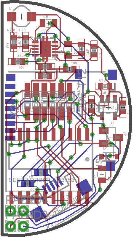
Below are 5:1 images of the Eagle files. They were fabricated via SeeedStudio's Fusion PCB service.
Top Board PCB
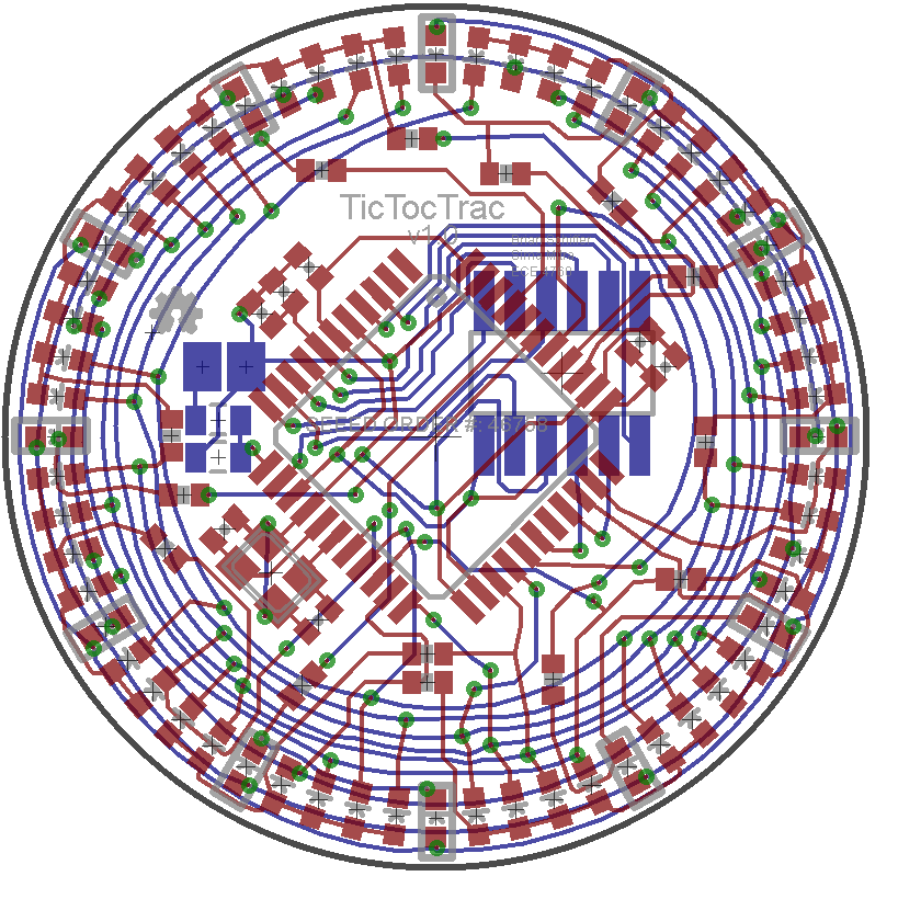
Bottom Board PCB
Bill of Materials
This is the complete list of all the electronics needed to construct a TicTocTrac v1.0. Datasheets for all parts can be found on the vendor website.
Item |
Part Number |
Description |
Price |
Quantity |
Total |
| Atmega32u4 | ATMEGA32U4-AU-ND | AVR 32K 16MHZ 44TQFP | $6.040 | 1 | $6.04 |
| Crystal | XC1812CT-ND | CRYSTAL 16.000 MHZ 20PF SMD | $1.690 | 1 | $1.69 |
| RTC | DS3234S#-ND | IC RTC W/TCXO 20-SOIC | $8.160 | 1 | $8.16 |
| LiPo Charger | MCP73831T-2ACI/OTCT-ND | IC CONTROLLR LI-ION 4.2V SOT23-5 | $0.680 | 1 | $0.68 |
| Boost Converter | 296-21663-1-ND | IC BOOST SYNC ADJ 1.2A 10SON | $3.900 | 1 | $3.90 |
| LED(red) | 754-1117-1-ND | LED 1.6X0.8MM 625NM RED CLR SMD | $0.078 | 60 | $4.68 |
| MOSFET | 568-1369-1-ND | MOSFET N-CH 60V 300MA SOT-23 | $0.150 | 1 | $0.15 |
| Diode | 1N914BWSCT-ND | DIODE 75V 150MA SOD323F | $0.360 | 1 | $0.36 |
| MicroUSB | H11634CT-ND | CONN RCPT MICRO USB B SMD R/A | $1.100 | 1 | $1.10 |
| MicroSD | HR1964CT-ND | CONN MICRO SD R/A PUSH-PUSH SMD | $2.960 | 1 | $2.96 |
| Battery | (sparkfun): PRT-00731 | PLOYMER LITHIUM ION BATTERY - 110mAh | $6.950 | 1 | $6.95 |
| Piezo Sensor | (sparkfun): SEN-10293 | PIEZO ELEMENT TAP SENSOR | $1.500 | 1 | $1.50 |
| Vibration Motor | (sparkfun): ROB-08449 | SHAFTLESS VIBRA MOTOR 2-3.6V | $4.950 | 1 | $4.95 |
| White PCB (top) | (SeeedStudios): PCB08511P | PCB 2 LAYER, 0.8MM THICK, WHITE | $1.990 | 1 | $1.99 |
| PCB(bottom) | (SeeedStudios): PCB08511P | PCB 2 LAYER, 0.8MM THICK,GREEN | $0.990 | 1 | $0.99 |
| 22Ohm | 311-22GRCT-ND | RES 22 OHM 1/10W 5% 0603 SMD | $0.010 | 2 | $0.02 |
| 33Ohm | RHM33KCT-ND | RES 33 OHM 1/4W 5% 0805 SMD | $0.083 | 1 | $0.08 |
| 100Ohm | 311-100GRCT-ND | RES 100 OHM 1/10W 5% 0603 SMD | $0.006 | 14 | $0.08 |
| 2kOhms | 311-2.0KGRCT-ND | RES 2.0K OHM 1/10W 5% 0603 SMD | $0.010 | 1 | $0.01 |
| 10kOhm | 311-10KGRCT-ND | RES 10K OHM 1/10W 5% 0603 SMD | $0.010 | 1 | $0.01 |
| 220kOhms | 541-220KSACT-ND | RES 220K OHM .25W 5% 0603 SMD | $0.202 | 2 | $0.40 |
| 1.0MOhm | RHM1.0MKCT-ND | RES 1.0M OHM 1/4W 5% 0805 SMD | $0.083 | 2 | $0.17 |
| 1.2MOhm | 311-1.20MHRCT-ND | RES 1.20M OHM 1/10W 1% 0603 SMD | $0.014 | 1 | $0.01 |
| 2.0MOhms | 311-2.00MHRCT-ND | RES 2.00M OHM 1/10W 1% 0603 SMD | $0.014 | 1 | $0.01 |
| 20pF | 490-1410-1-ND | CAP CER 20PF 50V 5% NP0 0603 | $0.056 | 2 | $0.11 |
| 0.1uF | 490-1532-1-ND | CAP CER 0.1UF 16V 10% X7R 0603 | $0.024 | 5 | $0.12 |
| 1uF | 490-1543-1-ND | CAP CER 1UF 10V 10% X5R 0603 | $0.052 | 2 | $0.10 |
| 4.7uF | 445-7482-1-ND | CAP CER 4.7UF 10V 10% X5R 0603 | $0.275 | 3 | $0.83 |
| 22uF | 445-6797-1-ND | CAP CER 22UF 16V 10% X5R 0805 | $0.880 | 2 | $1.76 |
| 2.2uH | 587-1648-1-ND | INDUCTOR 2.2UH 20% SMD | $0.340 | 1 | $0.34 |
| Male Connector | 952-1390-ND | Male Connector 1.27mm Pitch SMD | $1.750 | 1 | $1.75 |
| Female Connector | 952-1372-5-ND | Female Connector 1.27mm Pitch SMD | $3.340 | 1 | $3.34 |
| microSD card | Salvaged | 2GB microSD card | Free | 1 | $0.00 |
| Mini USB Cable | Salvaged | Mini USB to USB A Cable | Free | 1 | $0.00 |
| Total: | $55.26 |
Division of Labor
Brian
- Social login
- Data upload & graphing
- RTC
Sima
- Top and Bottom board eagle schematics
- Eagle3D renderings
- 3D case model
We both worked on the higher level design, PCB layout, the user interface, SD card reading/writing, and any other aspects of the project.
References
Time Perception
- A Walk Through Time - A NIST Physical Measurements Laboratory presentation on the history of time measurement.
- You Live in the Past - A YouTube video by vsauce about time perception and lost time.
- The Time Paradox - A look at the psychology of time perception.
- Through the Wormhole - A clip of the television show featuring time perception.
- 10 Ways Our Minds Warp Time - How time perception is warped by life-threatening situations, eye movements, tiredness, and more...
- The influence of music on consumers' temporal perceptions - A paper from the Journal of Consumer Psychology.
- The Effect of Computer Gaming on Subsequent Time Perception - A paper from the Journal of Psychosocial Research on Cyberspace.
- Why Does Time Fly By As You Get Older? - A segment from NPR's All Things Considered on time perception.
Technical
Schematic Design
- Eagle - Software for schematic and PCB design. We used a free edition: Eagle 6.10 Lite.
- Sparkfun Power Cell LiPo Charger/Booster - Eagle schematic of a Lipo charger using a boost converter on which we based our own schematic.
- Sparkfun DeadOn RTC DS3234 Breakout - Eagle schematic of the DS3234 Real Time Clock on which we based our own schematic.
PCB Design and Fabrication
- Eagle - Software for schematic and PCB design. We used a free edition: Eagle 6.10 Lite.
- SeeedStudio - Inexpensive PCB fabrication service.
Charlieplexing
- Charlieplexing (Wikipedia) - Introduction to charlieplexing.
- Charlieplexed LED Clocks Introduction - Example using charlieplexing on an LED watch.
Bidirection LEDs
- Very Low-Cost Sensing and Communication Using Bidirectional LEDs - The original Mitsubishi Electric Research Laborities paper.
- Multi-Touch Sensing through LED Matrix Displays - Using an LED display bidirectionally to optically detect finger touches.
- Multitouch LED Display - Multitouch LED display on an Arduino Stamp.
- Using Light Emitting Diode Arrays as Touch-Sensitive Input and Output Devices - Paper on bidirectional LEDs implemented with charlieplexing.
- Using Inexpensive LEDs as Optical Detectors - Lots of helpful hints for using LEDs as sensors.
Software
- AVR Studio - Free software for writing C code for the AVR architecture. We used AVR Studio 4.19.
- FatFs Generic FAT File System Module - FatFs is a generic FAT file system module which we used to read and files to the microSD card.
- DS3234 RTC Arduino Library - A great arduino library for the ds3234 RTC. We used this as a reference for our own library and also ported some of their functions to C.
3D Renderings
- Eagle3D - Free software for creating 3D image files (.pov) of an Eagle PCB.
- Eagle3D tutorial - Walkthrough for generating a .pov file using Eagle3D.
- POV-Ray - Free software for rendering a .pov file.
Website
- Raphaël - A small JavaScript library used for graphing and SVG images.
- Ketchup - A small jQuery Plugin for validating a form.
- YoxView - JQuerery image viewer plugin.
- Jainrain - Provides Social Login.